IGNITION SYSTEM TESTING: First test of our ignition system. Gaseous oxygen and propane, spark ignited.
System is designed to eventually use liquid propane with gaseous oxygen at 500 PSI, about 2% of main engine Wdot and O:F of 1:5.
But, wanting to make some noise and flame right away, we tested first with gaseous propane from a disposable camp stove cyclinder,
manually controlled by a single switch simultaneously cutting on/off the GOX, GPG and SPARKS.
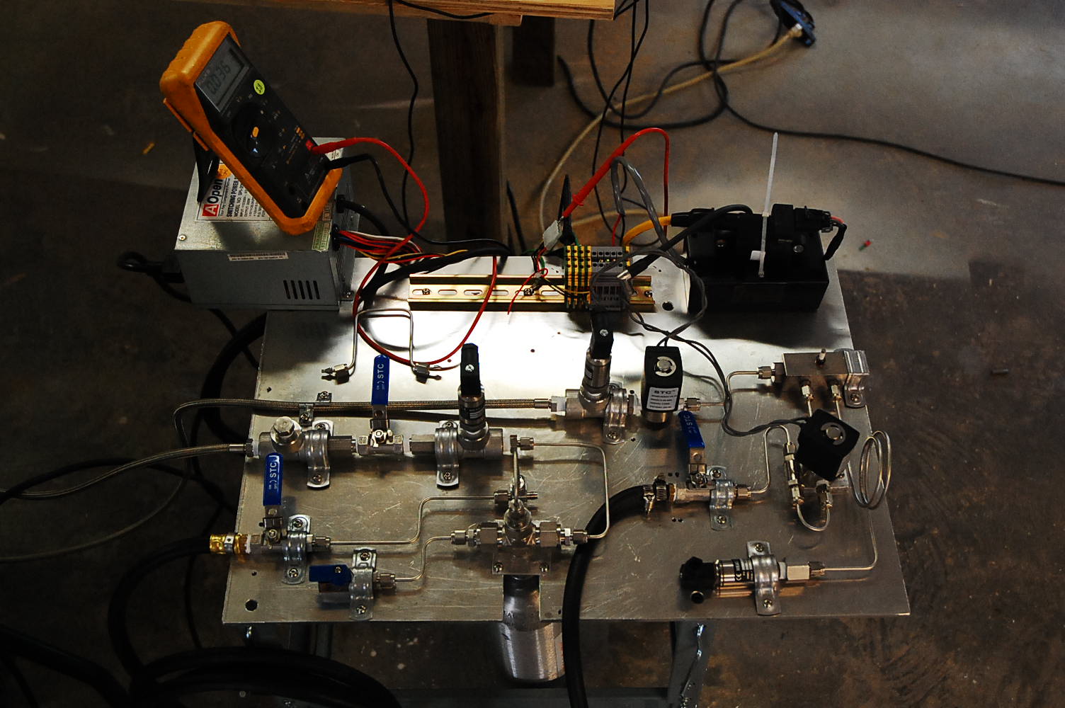
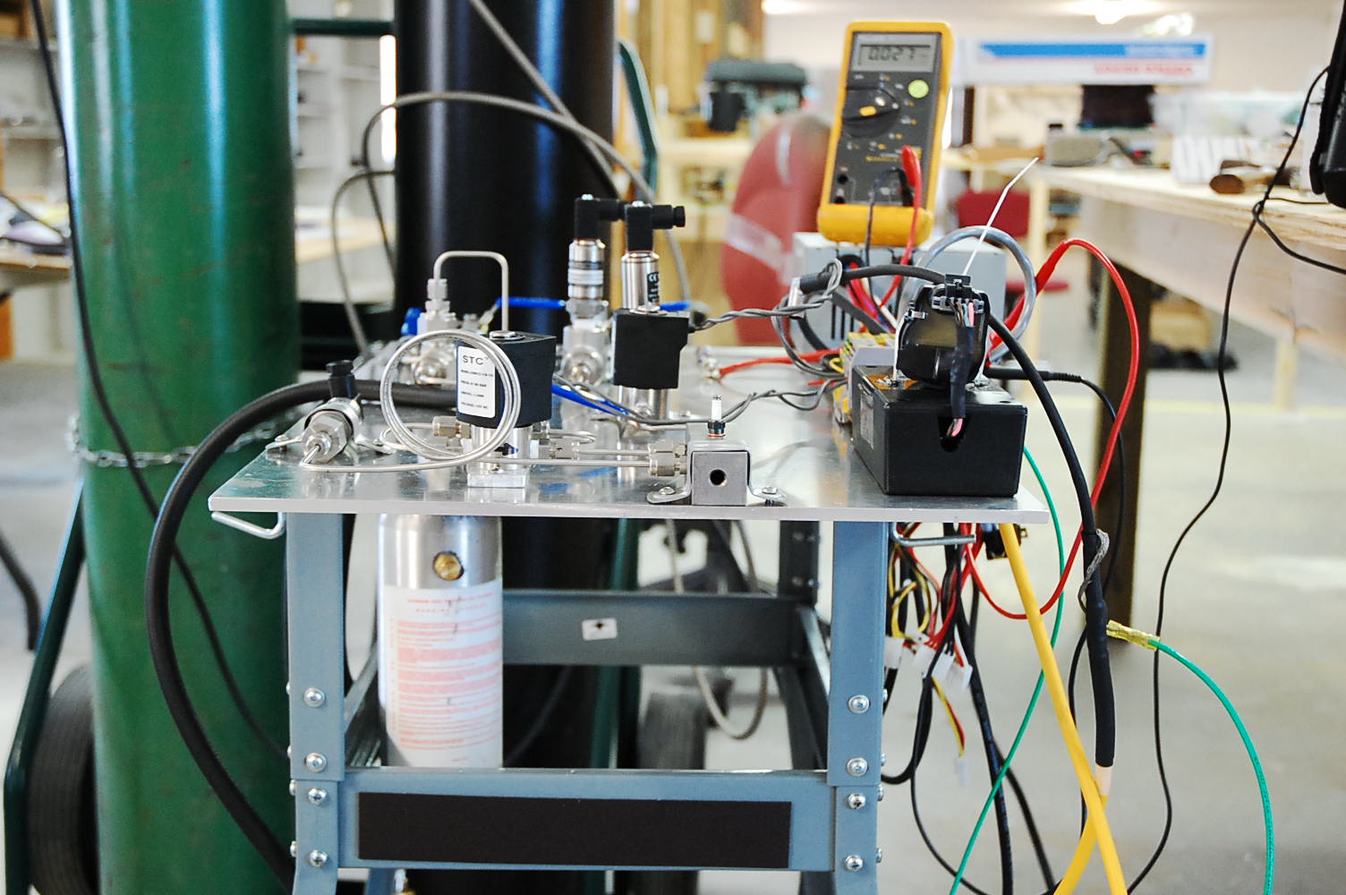
Here's an image, and description, of our test stand:
TEST STAND DESCRIPTION: Test stand is a 1/4" thick aluminum plate, about 16" x 24", on a wheeled stand.
At upper left (11 o'clock) is 12 VDC power supply.
Had a dedicated 50w 12vdc switcher, but it blew out during testing.
The 2 solenoids take about 1 amp each and the igniter takes about 2 amps.
Guess it didn't like the no-load/full-load excursions.
PC power supply is holding up ok, even with no other loads on it.
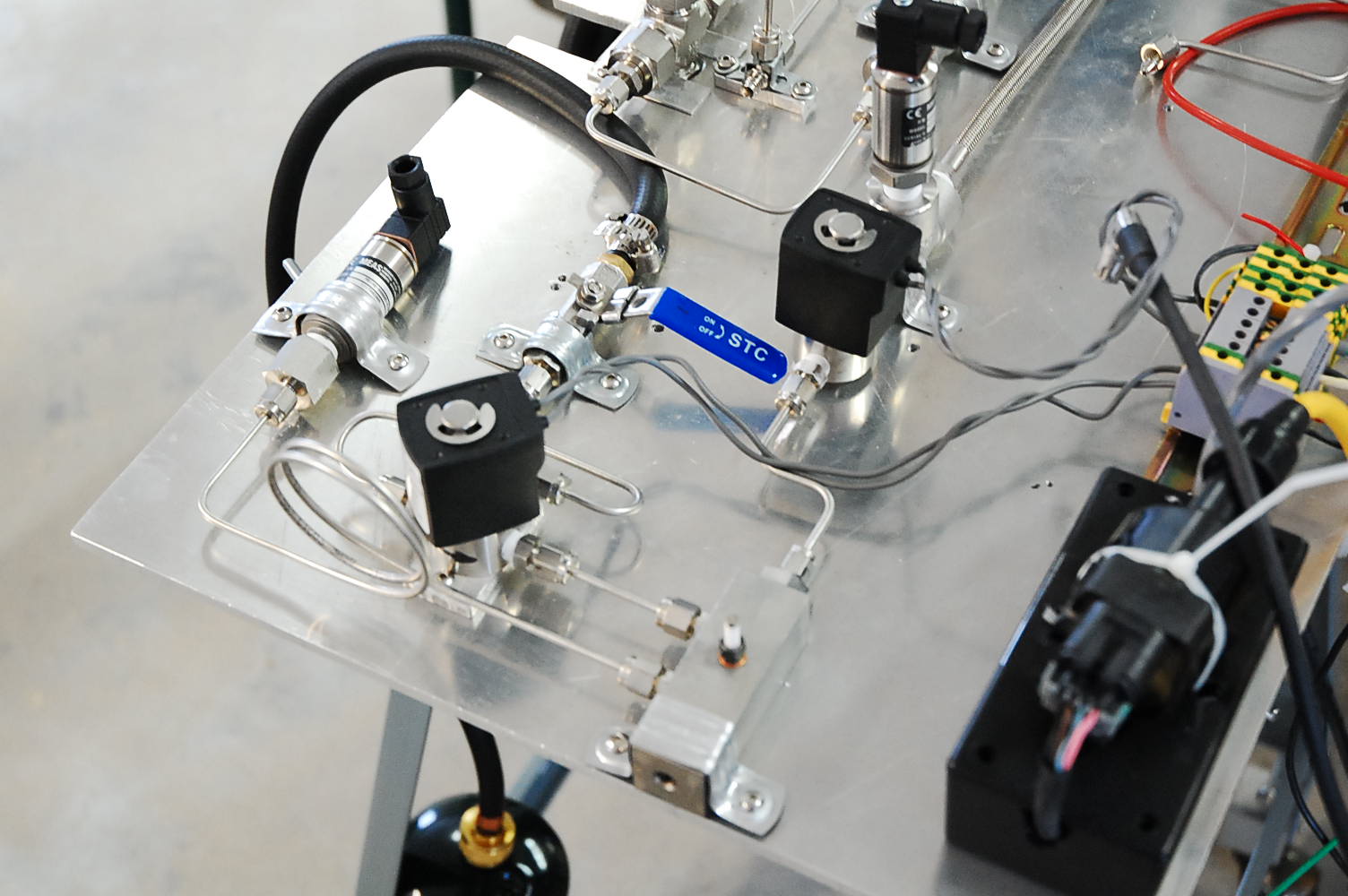
At the middle right (3 o'clock) is the igniter block.
It's a 1" square stainless steel bar, about 4 inches long with a 1/2" diameter central combustion chamber, converging to a 1/4" diameter, 1 inch long exit tube.
GOX is injected at the top, the GPG/LPG from the side, through which the GOX is blowing towards a baby spark plug (Rimfire VR2 1/4x32 thread),
about 1/2" down from GPG/LPG port. The spark plug is firing @ 100 Hz, 5 ms 50% duty cycle.
Right before the convergent section is a tap to measure chamber pressure.
It goes through a length of 1/8" SS tubing to reduce temperature of combustion gasses, before getting to the pressure transducer.
I imagine this would also reduce the high frequency response of the transducer somewhat.
GOX comes in through the stainless/teflon hose (US Hose 10' 3000 psi, 1/4" MNPT both ends, oxy cleaned ~ $65)
at the left middle of the stand (9 o'clock) to a pressure transducer and solenoid valve.
GOX and GPG/LPG each have a single injection orifice, made by tapping the inside of the Swagelok fittings,
screwing in a stainless hex set screw then drilling the set screw for the desired orifice size.
Since the propane orifice is sized (.028") for LPG (liquid, not gas), a lot less propane is flowing than planned, making the mix very oxygen rich - and HOT.
Design O:F ratio is 1:5.
For now, gaseous propane comes in through the black hose at the lower middle (6 o'clock) of the table.
It goes through an isolation ball valve, a 60 micron filter to the solenoid valve, then to the igniter.
Tubing is 1/8" stainless steel with Swagelok fittings. If it looks a little contorted, it's because: 1) I wanted to keep the GOX away from the GPG/LPG, separated by the nitrogen line.
2) I wanted tube lines to have some flex to avoid vibration problems and 3) This is the first time I've ever done tubing.
This puppy is LOUD, like a gun going off. After the first shot, I got my hearing protection.
But also from the length of the initial flame you can see on the video, ignition appears delayed.
Guess the 5 milliseconds between sparks might be a bit much.
Decreasing that (by increasing spark rep rate) should help.
The guy I got the spark plugs from also had an igniter that fired at like 2000 Hz. Wondered why so fast. Now I think I know.
And this is only with 250 PSI GOX and gaseous propane.
500 PSI GOX and LPG would likely be a lot more interesting, maybe even to the point of rapid disassembly.
Will increase the spark rate, and better secure the igniter to the table, and weight the table down some also.
The SOUTHWEST (lower left) quarter of the test stand supports Liquid propane (LPG) testing.
At room temperature, propane is a gas, with a vapor pressure of around 115 psi.
Chicora design tank pressure is 500 PSI (for Pc ~ 420 PSI).
At room temperature and 500 PSI, propane is a liquid and needs a pressuring gas to move it about.
In this case it's nitrogen gas coming in through the lower stainless steel hose at 9 o'clock on the test stand.
It goes through an isolation valve, pressure transducer and is introduced into the top of small aluminum pressure cylinder through a T fitting.
The small aluminum cylinder hanging below the table (6 o'clock) is initially charged with liquid propane through the black hose at the lower left (8 o'clock) of the test stand.
The hose has a REGO fitting at the other end to connect to the liquid supply side of a fork lift type propane cylinder.
These propane cylinders aren't rated for 500 psi which is why another tank is needed.
A brass spit valve on the side of the aluminum cylinder gives an indication of when we have enough liquid propane.
The system is initially nitrogen purged and vented through the lower left ball valve (7 o'clock).
The liquid propane enters the aluminum cylinder at the top of the big T fitting, through a 1/8" tube,
which extends through the fitting to the bottom of the cylinder.
Still have to get the pressure transducers wired in and a bigger power supply. Thermocouples are on order.
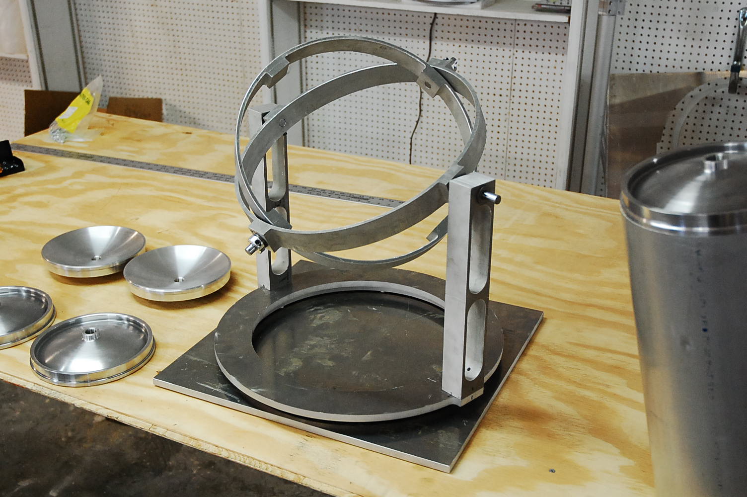
OTHER IMAGES:
Our flight electronics test stand to test electronics package in all orientations. Aluminum rings were water-jet cut from 1.5" thick 6061-T6 plate. The circular plate sits on a turn table for 360 rotation.
Not anodized yet. Will have vibrator attached to base plate.
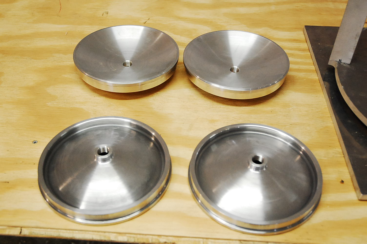
Propellant tank bulk heads, 8" diameter, 1.3 lbs each. Thick ring on exterior side for attaching inter-tank and fore/aft structures.
Solidworks says they're good to 500 PSI ... we'll see.
Still have to attach inlet diffusers and outlet strainers before welding to tank section.
Got 6 bulkheads and 3 short (16") tank sections with 1/8" thick wall to make 3 tanks. All are 6061-T6 aluminum.
One tank to test to destruction or 750 PSI, whichever comes first. Other 2 for LOX/LPG on static test stand and first test vehicle.
The 1/8" wall thickness is needed for strength at the welds, but not in the rest of the tank.
For flight weight tanks, about 1" in from the welds, we'll turn the wall thickness down to 1/16" thick (mandrel).
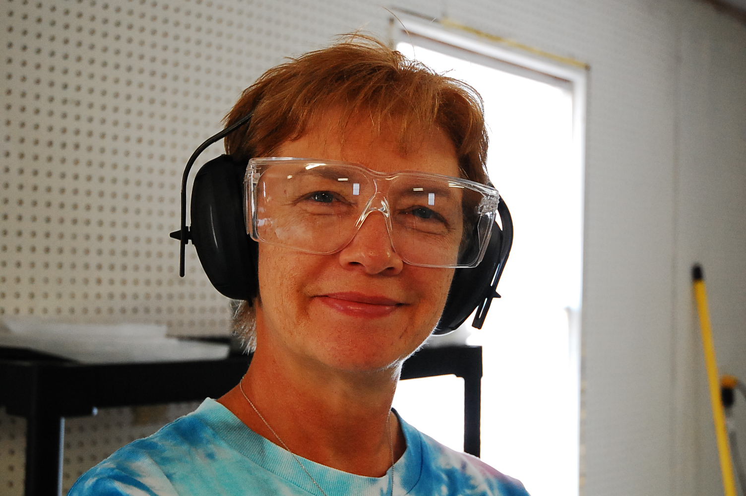
My Rocket Lady, very understanding and supportive.
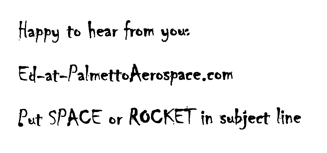
Apologies for the funky response image below.
And more apologies! This email address was not enabled till 11-OCT-2010.
Sorry! But it works now!
Replace the -at- with the at sign.