
 ASSEMBLING THE TEST STAND
PROJECT PEAK
 We're putting together the test stand in order to develop a 50 lbs thrust chamber as a part of
Project Peak
to develop guidance and stabilization systems, which are a necessary precursor to Project Chicora, which more and more reminds me of the song,
"There's a hole in the bucket, dear Liza ..."
We're using COTS LOX and LPG tanks with a smaller tank for pressurization gas (GN2 for now).
We're putting together the test stand in order to develop a 50 lbs thrust chamber as a part of
Project Peak
to develop guidance and stabilization systems, which are a necessary precursor to Project Chicora, which more and more reminds me of the song,
"There's a hole in the bucket, dear Liza ..."
We're using COTS LOX and LPG tanks with a smaller tank for pressurization gas (GN2 for now).
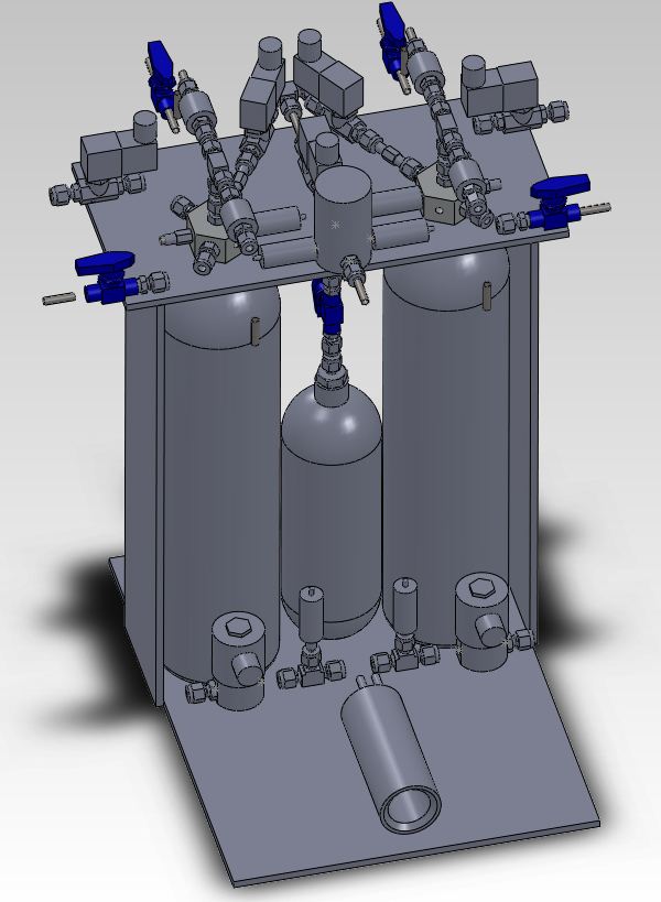
The test stand is to be pretty much self contained.
LOX, LPG and GN2 are loaded into onboard tanks, then the fill lines are disconnected.
Liquid LOX/LPG pass through the central tube at the top of the tank manifolds.
Thrust chamber is to fire horizontally on a free sprung table (not shown) with load cell for thrust measurements.
The whole assembly (tanks and all) is to be mounted on a load cell for propellant use measurements.
Once we have the propulsion pretty well characterized, we'll mount the engine vertically and start testing TVC and stabilization,
making the test stand into a VTVL type unit. Tanks should allow about 30 seconds of burn time, depending on how fuel rich we have to run to keep the uncooled chamber from burning out.
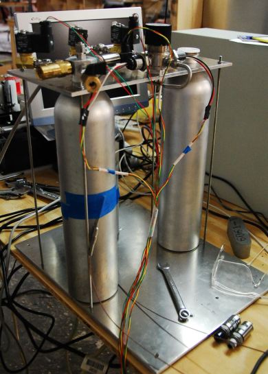
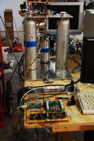 Here's the test setup in our shop. We've assembled and tested one side of the gas system: GN2 pressurization to the LPG tank.
In the foreground is one of our load cells on a test plate, and a bread board of the data acquisition and control electronics.
To test the thermocouples, I taped them temporarily to the tanks.
They showed a temperature rise as tanks were pressurized, and a temperature drop as tanks were vented.
I thought the heats would cancel: cooling while expanding gas from big tank into little one = heating from compressing gas in the little tank.
They did I'm sure - but not where I expected.
There was significant temperature rise (10 deg F) in the small tank pressurizing it to 2000 psi.
Ditto on the larger tanks pressurizing them to 500 PSI from the smaller GN2 tank.
Here's the test setup in our shop. We've assembled and tested one side of the gas system: GN2 pressurization to the LPG tank.
In the foreground is one of our load cells on a test plate, and a bread board of the data acquisition and control electronics.
To test the thermocouples, I taped them temporarily to the tanks.
They showed a temperature rise as tanks were pressurized, and a temperature drop as tanks were vented.
I thought the heats would cancel: cooling while expanding gas from big tank into little one = heating from compressing gas in the little tank.
They did I'm sure - but not where I expected.
There was significant temperature rise (10 deg F) in the small tank pressurizing it to 2000 psi.
Ditto on the larger tanks pressurizing them to 500 PSI from the smaller GN2 tank.
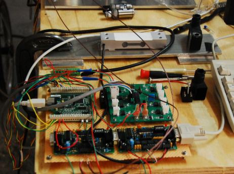
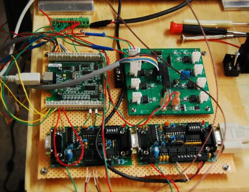 This is the breadboard of our data acquisition and control electronics.
I'm using a Windows XP desk top computer with Borland CBuilder for now (because I'm familiar with it).
Eventually we'll move to an embedded computer and wireless telemetry/control system as we get closer to the VTVL stage.
This will likely only last till we integrate the ignitor spark generator and see what the noise does to us.
This is the breadboard of our data acquisition and control electronics.
I'm using a Windows XP desk top computer with Borland CBuilder for now (because I'm familiar with it).
Eventually we'll move to an embedded computer and wireless telemetry/control system as we get closer to the VTVL stage.
This will likely only last till we integrate the ignitor spark generator and see what the noise does to us.
Boards, clockwise from upper left, are: A USB DAQ; Our
SOLDRV high side solenoid driver; A Weeder WTAIN (Analog Input) and; A Weeder WTTCI (Thermocouple interface). They're all powered from a single 24vdc supply.
The USB DAQ is used to drive the solenoids (via SOLDRV) and for inputs from 7 pressure transducers.
The Weeder units I had laying around and turned out to be just what we needed.
The WTAIN has bridge inputs (4) and sufficient excitation to drive the Aerocon load cells.
The WTTCI has built in calibrations for all common thermocouple types (we're using Nanmac ungrounded E types) and gives temps directly in degrees F or C.
Throughput isn't great (it's an RS-232 ASCII interface fixed at 9600 baud) but we get 20-30 readings a second from the TC's and loadcells which should be fine. We're reading each PX at 1000 Hz.
Hadn't used load cells or thermocouples before, but they came right up and are responding as expected.
 Here's the Aerocon 50kg load cell we're using, on a plate for testing. Looks like the load cell has almost 3mm of deflection with 50Kg load.
(I got a spare for when we break this one.) The discrete wires are all Teflon insulated.
Here's the Aerocon 50kg load cell we're using, on a plate for testing. Looks like the load cell has almost 3mm of deflection with 50Kg load.
(I got a spare for when we break this one.) The discrete wires are all Teflon insulated.
 The cylinders we're using
(Catalina 1602) for LOX/LPG tanks have a single 1" threaded hole.
I made a threaded manifold (learning how to cut threads on a lathe in the process) from 1.75" aluminum hexagonal bar stock.
The Swagelok connections are straight thread o-ring sealed connections (learned about counter-bores).
The cylinders we're using
(Catalina 1602) for LOX/LPG tanks have a single 1" threaded hole.
I made a threaded manifold (learning how to cut threads on a lathe in the process) from 1.75" aluminum hexagonal bar stock.
The Swagelok connections are straight thread o-ring sealed connections (learned about counter-bores).
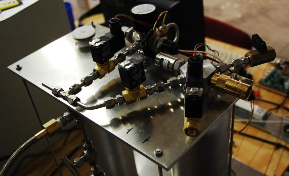
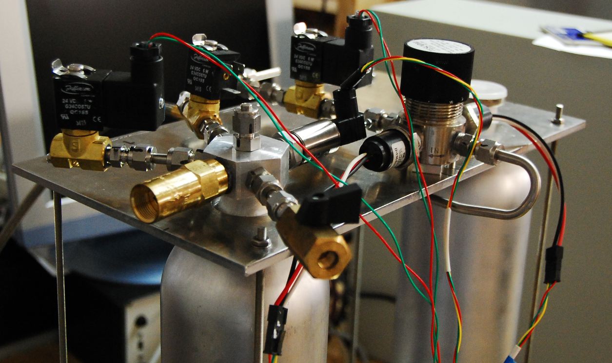
Clockwise from the bottom, the components on the manifold are:
Manual vent valve. Likely will need this for LOX filling. A kevlar line attached to it
will be our remote manual vent mechanism #1 (#2 will be a .308).
REGO relief valve set at 550 PSI. Tested, works fine.
Vent valve, Jefferson 2026 solenoid valve with 1.25mm orifice. We'll see if this is big enough.
GN2 pressurization supply valve.
Tank pressure transducer.
The 6th face of the manifold isn't used but I'm thinking I'll put a thermocouple up there with a Swagelok bored through connector.
The liquid line (shown plugged in the image) goes down the middle of the manifold to the bottom of the tank and an attached strainer.
Higher up on the line will be clamped a diffuser (small circular plate) to direct pressurization gas to the sides of the tank instead of blowing straight down.
To the right of the manifold is a TESCOM BB1 regulator. GN2 at high pressure comes in via the 1/4" line under the aluminum plate. GN2 at ~ 400 PSI comes out the other side to the pressurization supply valve that feeds separate pressurization valves for LOX and LPG.
Honeywell MLH type pressure transducers monitor input and output pressures on the regulator which can come with extra holes for this.
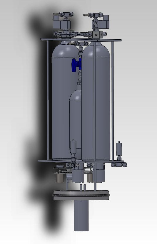
The vent lines (3 for each tank) come out on opposites sides of the test stand. I'd like to at least pipe vented LPG up and away somehow.
And support the valves and things which are just hanging off the tube connections.
 The whole platform is intended to sit on a load cell for measuring propellant fill before hand, and expenditure after firing.
Likely won't work well while the TC is firing (may not work well regardless) but should stabilize afterwards to see how much has been used.
The whole platform is intended to sit on a load cell for measuring propellant fill before hand, and expenditure after firing.
Likely won't work well while the TC is firing (may not work well regardless) but should stabilize afterwards to see how much has been used.
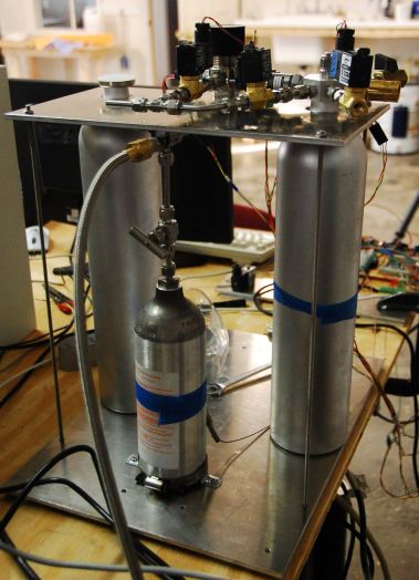 Rear of the test stand showing the smaller GN2 tank. A Luxfer CO2 cylinder rated at 1800 psi working pressure. It's filled from a larger GN2 supply tank though the line shown. This is intended to provide purge gas and initial tank pressurization. Then the smaller GN2 tank is isolated while this fill line is removed and the connection sealed with a plug.
 Rear of the manifold showing the GN2 pressurization gas connections. A 1/4" solid rod blocked off the unused other side quite nicely.
NEXT STEPS FOR PROJECT PEAK:
Add liquid side
Add spark generator - suppress electrical noise
Test with H20
Test with LN2 - venting capacity, sealing at cryo temps
Add the other propellant side: gas and liquid.
Develop and test the 50 lbs F chamber with liquid propellants at operational pressures - make some shock diamonds.
Embedded PC and wireless data/control
TVC - electromechanical, with flexible propellant ducts
Tethered platform with guidance
And then on to PROJECT CHICORA!
Apologies for the funky response image below. Replace the -at- with the at sign.
Home
 Here's the test setup in our shop. We've assembled and tested one side of the gas system: GN2 pressurization to the LPG tank.
In the foreground is one of our load cells on a test plate, and a bread board of the data acquisition and control electronics.
To test the thermocouples, I taped them temporarily to the tanks.
They showed a temperature rise as tanks were pressurized, and a temperature drop as tanks were vented.
I thought the heats would cancel: cooling while expanding gas from big tank into little one = heating from compressing gas in the little tank.
They did I'm sure - but not where I expected.
There was significant temperature rise (10 deg F) in the small tank pressurizing it to 2000 psi.
Ditto on the larger tanks pressurizing them to 500 PSI from the smaller GN2 tank.
Here's the test setup in our shop. We've assembled and tested one side of the gas system: GN2 pressurization to the LPG tank.
In the foreground is one of our load cells on a test plate, and a bread board of the data acquisition and control electronics.
To test the thermocouples, I taped them temporarily to the tanks.
They showed a temperature rise as tanks were pressurized, and a temperature drop as tanks were vented.
I thought the heats would cancel: cooling while expanding gas from big tank into little one = heating from compressing gas in the little tank.
They did I'm sure - but not where I expected.
There was significant temperature rise (10 deg F) in the small tank pressurizing it to 2000 psi.
Ditto on the larger tanks pressurizing them to 500 PSI from the smaller GN2 tank.
 This is the breadboard of our data acquisition and control electronics.
I'm using a Windows XP desk top computer with Borland CBuilder for now (because I'm familiar with it).
Eventually we'll move to an embedded computer and wireless telemetry/control system as we get closer to the VTVL stage.
This will likely only last till we integrate the ignitor spark generator and see what the noise does to us.
This is the breadboard of our data acquisition and control electronics.
I'm using a Windows XP desk top computer with Borland CBuilder for now (because I'm familiar with it).
Eventually we'll move to an embedded computer and wireless telemetry/control system as we get closer to the VTVL stage.
This will likely only last till we integrate the ignitor spark generator and see what the noise does to us.
 Here's the Aerocon 50kg load cell we're using, on a plate for testing. Looks like the load cell has almost 3mm of deflection with 50Kg load.
(I got a spare for when we break this one.) The discrete wires are all Teflon insulated.
Here's the Aerocon 50kg load cell we're using, on a plate for testing. Looks like the load cell has almost 3mm of deflection with 50Kg load.
(I got a spare for when we break this one.) The discrete wires are all Teflon insulated.
 The cylinders we're using
(Catalina 1602) for LOX/LPG tanks have a single 1" threaded hole.
I made a threaded manifold (learning how to cut threads on a lathe in the process) from 1.75" aluminum hexagonal bar stock.
The Swagelok connections are straight thread o-ring sealed connections (learned about counter-bores).
The cylinders we're using
(Catalina 1602) for LOX/LPG tanks have a single 1" threaded hole.
I made a threaded manifold (learning how to cut threads on a lathe in the process) from 1.75" aluminum hexagonal bar stock.
The Swagelok connections are straight thread o-ring sealed connections (learned about counter-bores).
 The whole platform is intended to sit on a load cell for measuring propellant fill before hand, and expenditure after firing.
Likely won't work well while the TC is firing (may not work well regardless) but should stabilize afterwards to see how much has been used.
The whole platform is intended to sit on a load cell for measuring propellant fill before hand, and expenditure after firing.
Likely won't work well while the TC is firing (may not work well regardless) but should stabilize afterwards to see how much has been used.
 Rear of the test stand showing the smaller GN2 tank. A Luxfer CO2 cylinder rated at 1800 psi working pressure. It's filled from a larger GN2 supply tank though the line shown. This is intended to provide purge gas and initial tank pressurization. Then the smaller GN2 tank is isolated while this fill line is removed and the connection sealed with a plug.
 Rear of the manifold showing the GN2 pressurization gas connections. A 1/4" solid rod blocked off the unused other side quite nicely.