This is our first stab at a 50 lbs thrust chamber. Propane and oxygen, steel chamber, stainless steel injector, graphite nozzle,
direct spark ignition, with excess fuel injected along walls to keep them cool.
Encountering difficulty last year in making tanks for Project Chicora, we backed up a bit to work on the other things
that need doing such as TVC, guidance and telemetry.
And decided to do what we can with what we have propulsion wise. Thus Project Peak (named after the smallest town in South Carolina).
Peak will be a VTVL test bed for TVC, guidance and telemetry in a rocket environment.
We'll use OTS tanks (CO2) and valves. Size is pretty much determined by the LOX we can flow through an OTS (GEMS) cryo valve.
Here are the video clips.
Second Fire One was on April 12, 2011, a significant day for many reasons.
We didn't get to launch Chicora as I had hoped, but at least we made some progress - and some more fire!
We burned the engine for about 30 seconds, but we flubbed around afterwards and lost the video file.
Second Fire Two was on the next day, around noon time, very bright in the sandhills region of South Carolina where our shop is located.
We disassembled the engine afterwards. Everything looked good. A little soot on the spark plug.
Second Fire Three was in the evening of the third day, after reassembly of the engine, to see if we could get better video in the evening.
Smoke from the spark plug was from the insulating grease in the spark plug hood.
At the end of the video you can see the graphite nozzle glowing red.
No throat erosion could be measured or seen and no cracking of the graphite nozzle. But we were just running gas/gas 100/150 psi.
It was a very lean - and hot - GOX/GPG* mix in the chamber, which was way overbore for the amount of gas we were passing through it. :-)
Thermal spot checks on the chamber exterior a minute or so after the last burn showed a temp of 480 deg F.
A little Bostic Stainless Steel Never-Seez on all the screw and spark plug threads worked fine, all unthreaded easily.
Here's our test stand, 1/4" thick aluminum plate (what we used for our First Fire igniter tests) with the thrust chamber on the right.
All gas for this first test. GOX coming from a tank at the left, and GPG* from the little camp cylinder.
The steel round bar stock shown weighing down the front of the table is what we made the chamber from, un-pedigreed low carbon steel.
We got it from the local steel supply company around the corner, that had a pile of drops outside, very rusty as you can see.
We tested this puppy outdoors since our shop used to be an old hardware store and the interior walls are painted 1/8" masonite peg board - not very fire resistant.
AND BEFORE THAT ...
Ordered some graphite rod from TheGraphiteStore, but they flubbed up the order -
"Where's that stuff that was supposed to be here 2 days ago? Oh! Sorry, those are out of stock, but I ca<"click">".
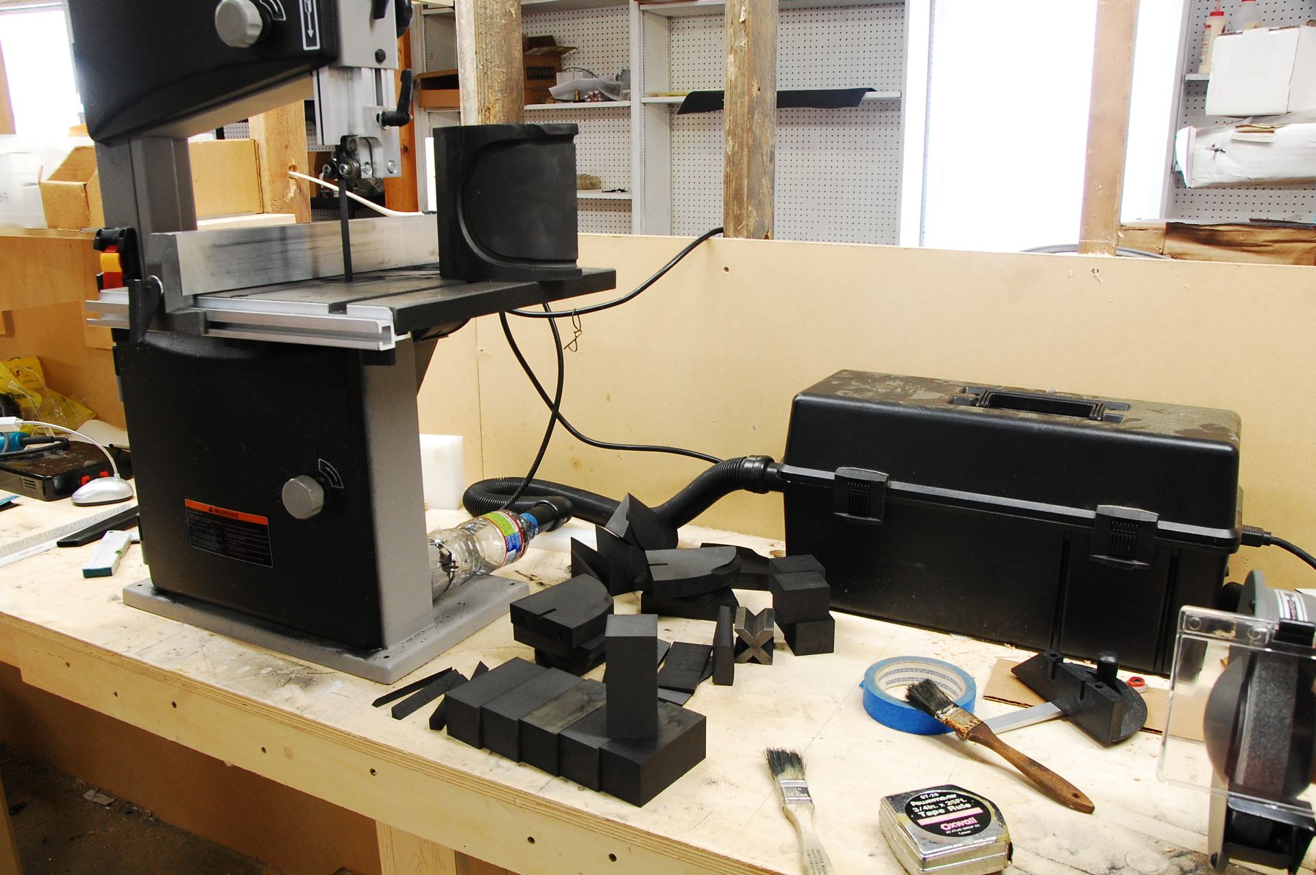
Went to the eBay "maybe someday" hoard and found some graphite quarter rounds I had bought years ago. Very fine grained, almost like black aluminum.
They cut very nicely on the table top band saw to 1.6" x 1.6" x 3.5" blocks.
Managed to get three blocks from each big piece (seen sitting on table of band saw). Each block will make two 1.5" OD x 1.5" long nozzles.
The toner vacuum with water bottle adapter worked well, very little graphite dust escaped.
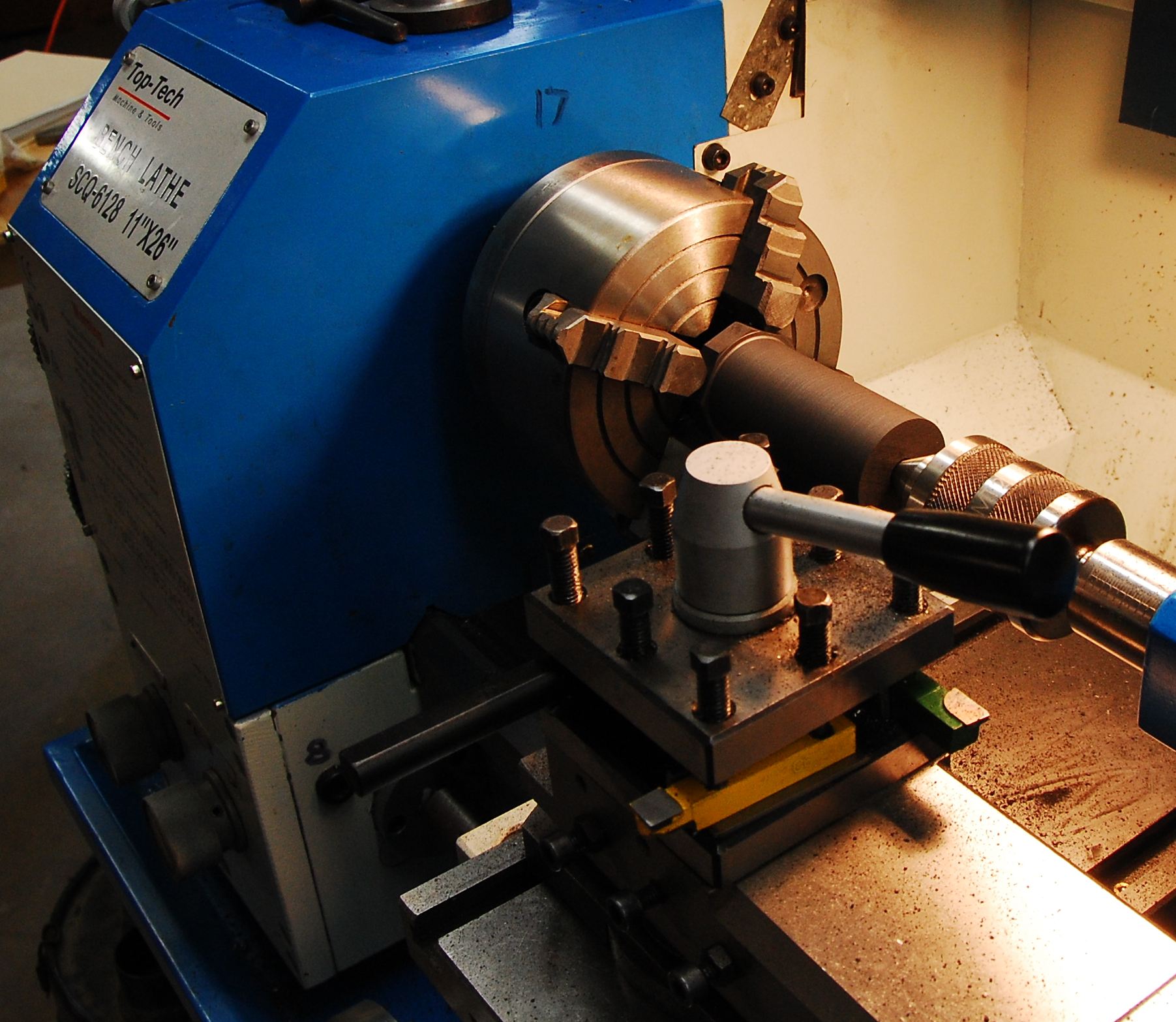
I sawed the square graphite block into an octagon to cut down the amount of graphite to be removed by the lathe.
Getting it dialed in was a chore though.
Holding a vacuum nozzle under the cutting tool while cutting kept the graphite dust to a minimum on the lathe. Quite manageable.
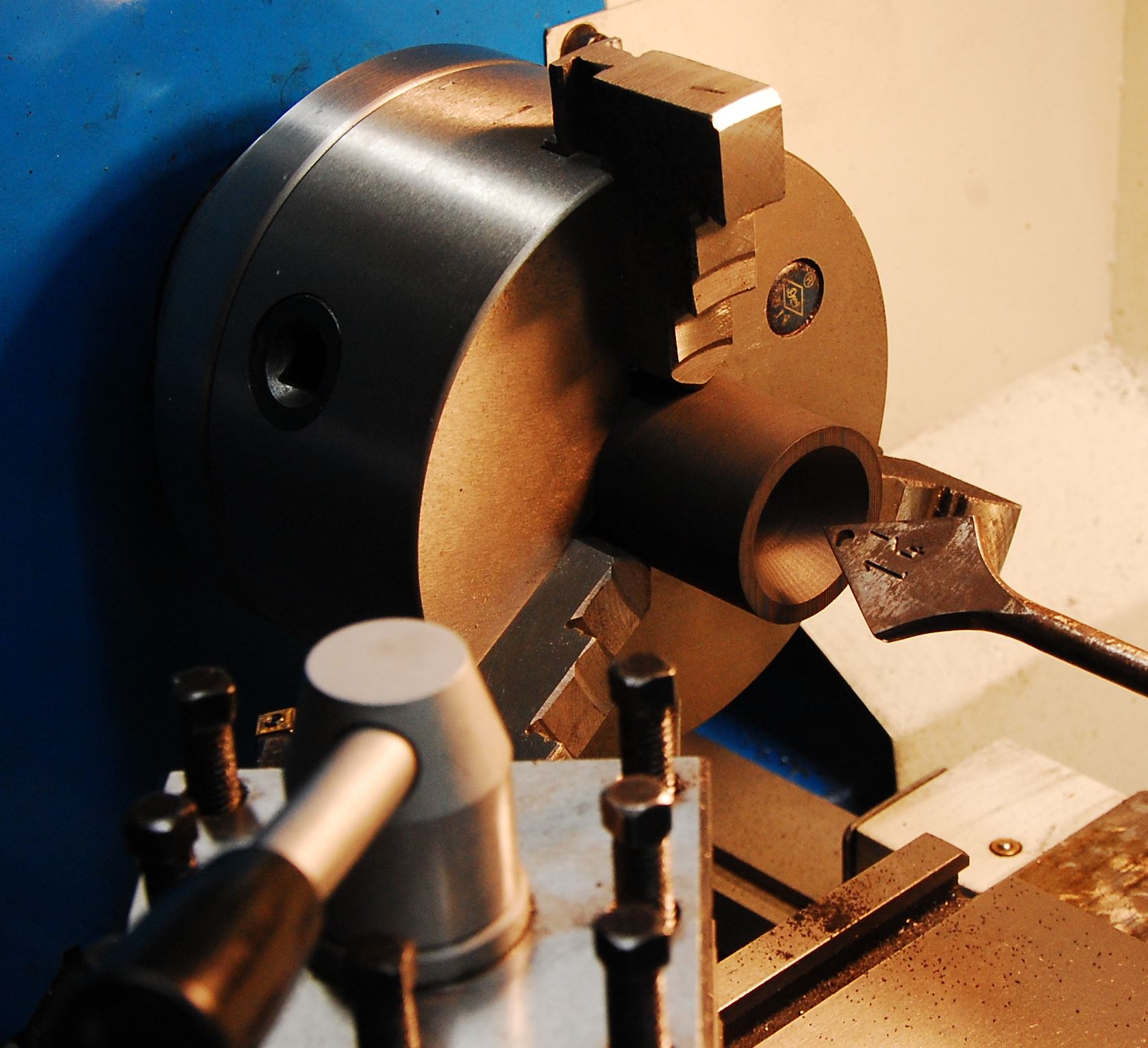
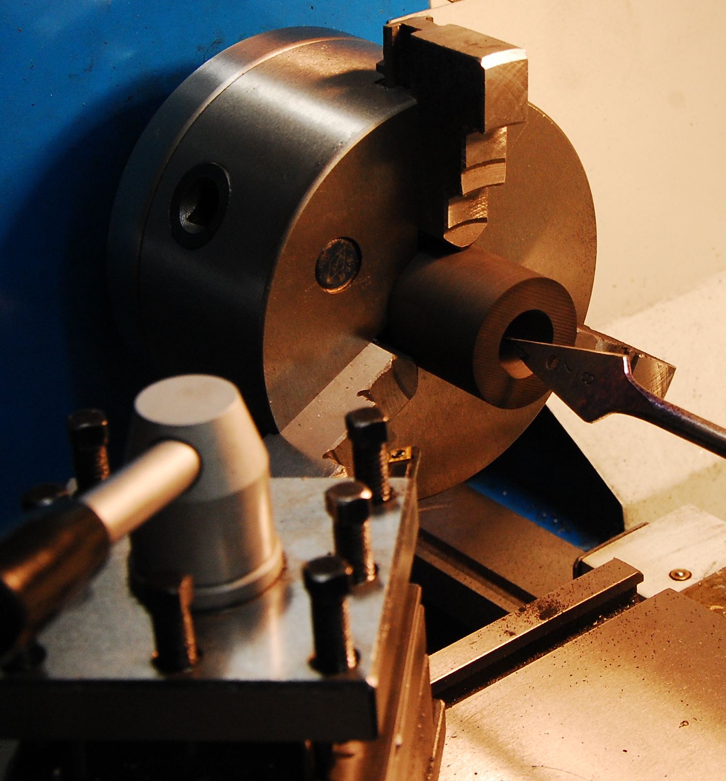
After rounding, I bored the graphite bar through with a nozzle throat diameter hole (.4").
Then put it on the band saw to make two 1.5" long cylinders.
I ground down wood bits to 30 and 15 degree angles to bore out the convergent and divergent nozzle sections respectively. Worked fine.
I scratched my head for a moment trying to figure how to contour the nozzle exit to fit the 45 degree countour of the restraining cap.
Then I remembered the lathe would spin in reverse.
Was able to keep the same tool setup from boring the internal 45 degree angle
on the nozzle retaining cap (see next image below) for the external 45 degree angle on the nozzle exit. so they matched well.
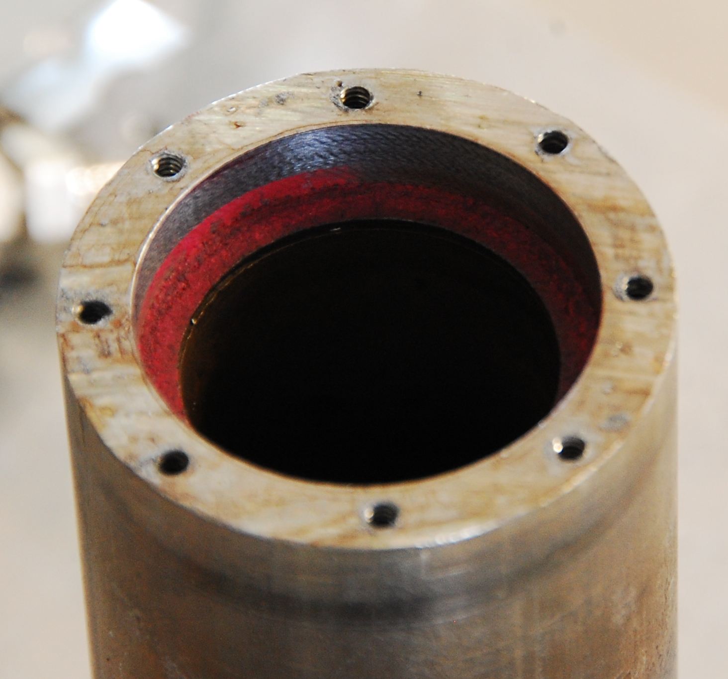
Components before firing. Exit end of the thrust chamber showing the graphite nozzle chamber with red faced graphite seal.
Chamber is 2" OD, 1.25" ID 1020 steel tube stock.
The walls are .375" thick, so had to mill it down considerably to get our baby spark plug some exposure inside, and access to the wrench flats.
The nozzle retaining cap is from the rusty steel round stock we have, that I remembered to turn down to 2" before cutting off a hunk (unlike the injector cap).
Eight 4-40 cap screws give us plenty of seal loading, up to 1000 PSI, but only if you drill and tap the holes deep enough.
The rings around the perimeter at either end of the chamber are from the steady rest I used when boring the inside.
The chamber side of the nozzle showing the seal bearing surface.
Nozzle inserted in chamber. The 45 degree contour matches the contour on the retaining cap.
Stainless steel injector plate. A 1.5" OD SS disk we got here.
They have steel, stainless, aluminum and brass disks in sizes from 1" to 12" OD, good prices, no minimums.
This is the fuel chamber, with center hole for GOX/LOX post and GPG/LPG coaxial injection.
Wall cooling GPG/LPG holes around the perimeter.
These were #71 drill holes in SS, we lost a few bits and relocated the holes.
Not sure how the spacing of the holes got messed up. Don't have an indexing plate, these are manually scribed and drilled.
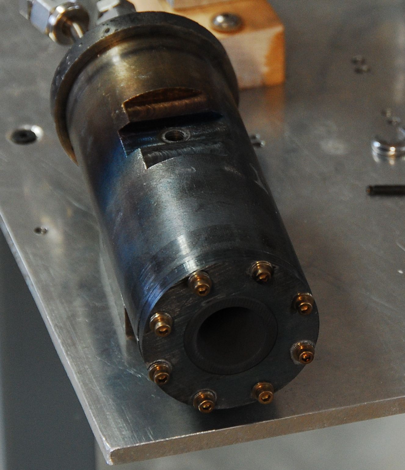
The milled flat on side of the chamber is for support on a steel block on our test stand (see next image below).
A seal, like the one shown, is below the injector plate bearing on a shoulder in the chamber.
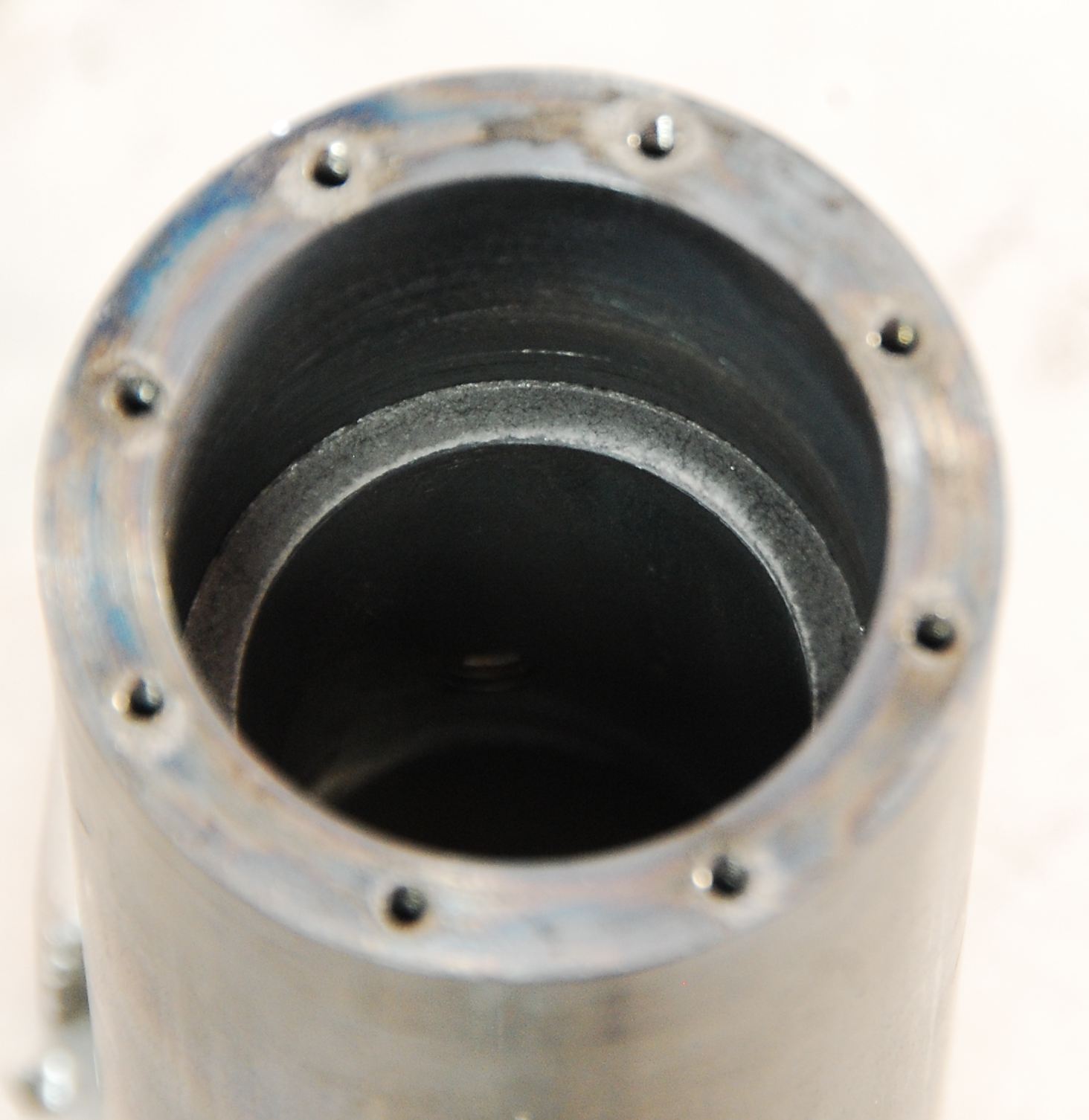
Chamber after Second Fire Two, starting disassembly. After Second Fire Three, the chamber was a nice gray/black all the way up.
You can see the top plate was made from our unturned rusty stock, 2.25" OD.
It was the first work I had done on the lathe and was supposed to be the sacrificial practice piece, but turned out OK otherwise, so I used it.
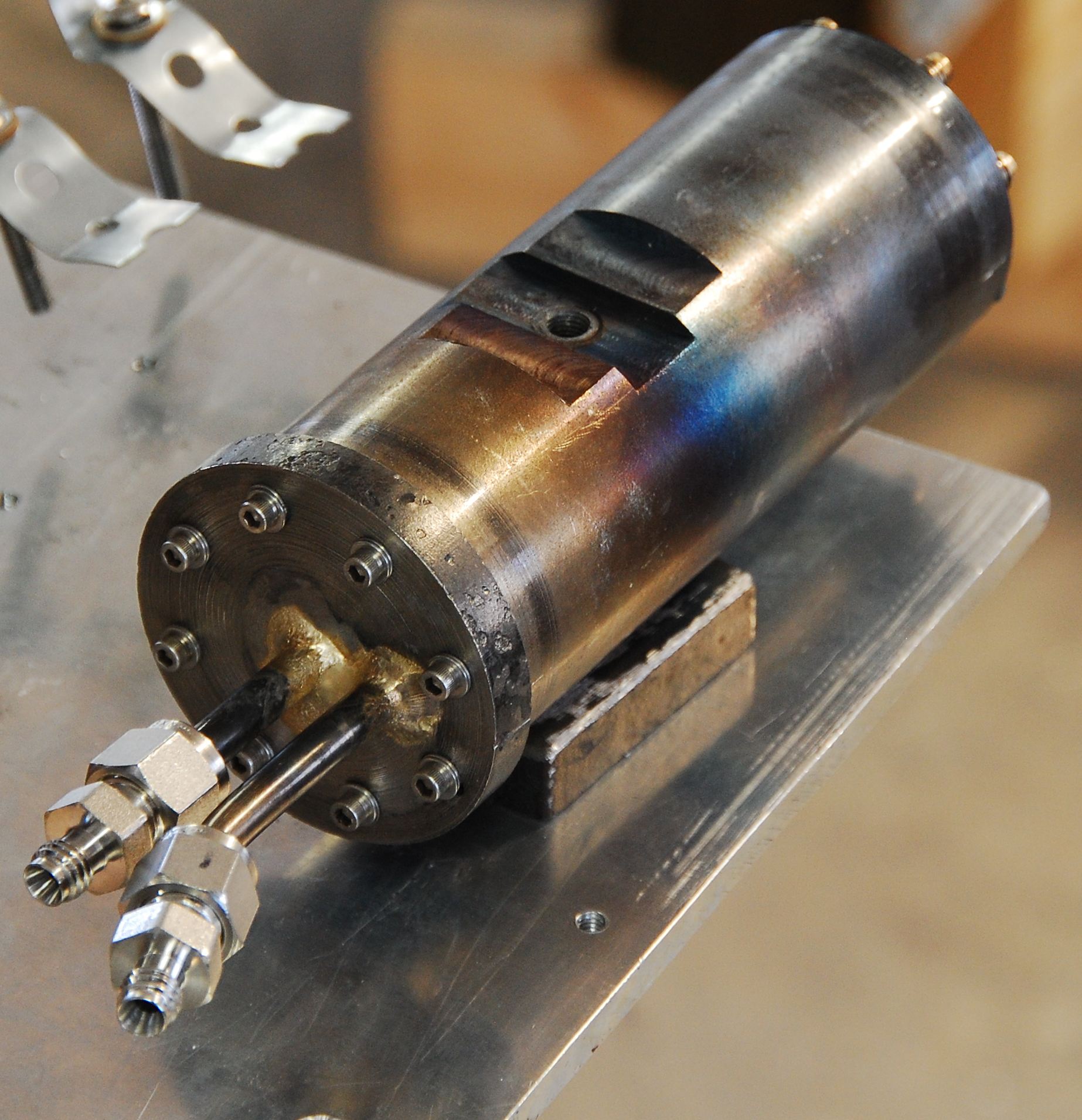
Top plate with brazed 1/4" SS GOX (center) and GPG inlet tubes with Swagelok fittings. This was our first attempt at brazing.
We have a small GOX/GPG torch, which had a hard time heating up this oversized hunk of metal.
Subsequent chambers will mount to the supporting structure through this top cap.
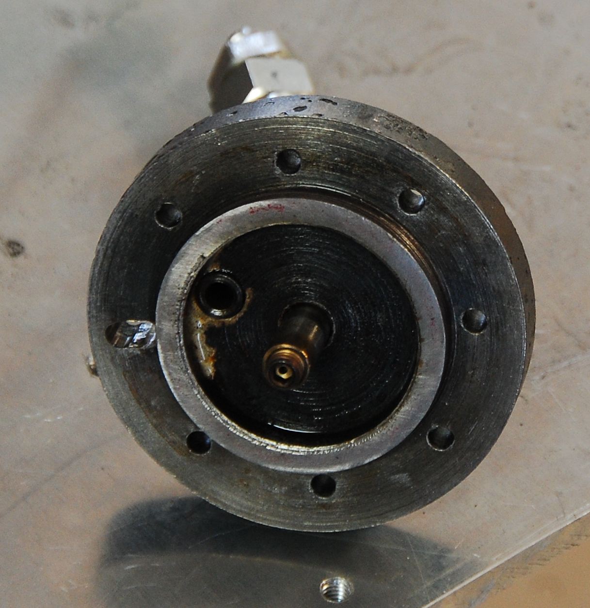
Top plate showing GPG inlet and GOX post. Well coked after heat soaking after shutdown.
We're using straight propane gas from a camping cylinder with who knows what in it besides C3H8.
We're not planning on regen cooling at this point so hopefully fuel purity isn't too much of a concern
(though we do have filter before the injectors) unless the injector holes gunk up after shutdown.
The inner ring is 1.5" OD and 1.25" ID and presses a seal against the SS injector plate which is 1.5" OD.
The GOX/LOX post is heavy wall (.049" thick) .25" OD SS tubing. We tapped it 10-32 and used a SS set screw into which we drilled the LOX orifice.
Wanted the setscrew flush with the tube end, but when tapping I felt I was awful close to breaking the tap so quit.
Turns out, the .15 ID is tap drill size for 10-24 but the 10-32 should be bigger, .16".
Forgot to bend the fuel tube before brazing, but managed to get it bent enough to put both Swagelok's on without interference.
Chamber side seal for the injector plate seemed to have some blow by. Will have to make sure the threaded holes are deep enough so we can get some clamping pressure on the seal
Ditto for the exit end seal, though a little blow by to equalize pressure between nozzle interior/exterior may be good.
SEALS: I use three 1.5" OD 1.25" ID x .062" thick graphite type gasket seals in this unit.
One on the chamber side of the graphite nozzle (see image above) and two on either side of the injector plate.
We got our graphite seals from Independent Sealing Co. in Philadelphia.
Lee Muller is very easy to work with, and if they have dies in stock (he has a lot of them) he can turn seals around quickly and cheaply.
I told him what I needed and he asked how many I wanted. I told him $50 worth. He laughed and sent me 17 seals the next day.
He's happy to take your material and die cut it also.
NEXT STEPS FOR PROJECT PEAK:
Instrument the test stand for pressures, flows, temps and thrust
Sequencing under computer control
Wireless data/control
LOX and LPG replacing GOX/GPG
TVC - an electromechanical system, with flexible propellant ducts
Free platform with guidance
And then on to PROJECT CHICORA!
* GPG is Gaseous Petroleum Gas - redundant maybe, but that's what I call it to distingish from liquid phase Liquified Petrolum Gas, propane.
Apologies for the funky response image below. Replace the -at- with the at sign.


 This is our first stab at a 50 lbs thrust chamber. Propane and oxygen, steel chamber, stainless steel injector, graphite nozzle,
direct spark ignition, with excess fuel injected along walls to keep them cool.
This is our first stab at a 50 lbs thrust chamber. Propane and oxygen, steel chamber, stainless steel injector, graphite nozzle,
direct spark ignition, with excess fuel injected along walls to keep them cool.
 Here's our test stand, 1/4" thick aluminum plate (what we used for our First Fire igniter tests) with the thrust chamber on the right.
All gas for this first test. GOX coming from a tank at the left, and GPG* from the little camp cylinder.
The steel round bar stock shown weighing down the front of the table is what we made the chamber from, un-pedigreed low carbon steel.
We got it from the local steel supply company around the corner, that had a pile of drops outside, very rusty as you can see.
Here's our test stand, 1/4" thick aluminum plate (what we used for our First Fire igniter tests) with the thrust chamber on the right.
All gas for this first test. GOX coming from a tank at the left, and GPG* from the little camp cylinder.
The steel round bar stock shown weighing down the front of the table is what we made the chamber from, un-pedigreed low carbon steel.
We got it from the local steel supply company around the corner, that had a pile of drops outside, very rusty as you can see.
 Ordered some graphite rod from TheGraphiteStore, but they flubbed up the order -
"Where's that stuff that was supposed to be here 2 days ago? Oh! Sorry, those are out of stock, but I ca<"click">".
Went to the eBay "maybe someday" hoard and found some graphite quarter rounds I had bought years ago. Very fine grained, almost like black aluminum.
They cut very nicely on the table top band saw to 1.6" x 1.6" x 3.5" blocks.
Managed to get three blocks from each big piece (seen sitting on table of band saw). Each block will make two 1.5" OD x 1.5" long nozzles.
The toner vacuum with water bottle adapter worked well, very little graphite dust escaped.
Ordered some graphite rod from TheGraphiteStore, but they flubbed up the order -
"Where's that stuff that was supposed to be here 2 days ago? Oh! Sorry, those are out of stock, but I ca<"click">".
Went to the eBay "maybe someday" hoard and found some graphite quarter rounds I had bought years ago. Very fine grained, almost like black aluminum.
They cut very nicely on the table top band saw to 1.6" x 1.6" x 3.5" blocks.
Managed to get three blocks from each big piece (seen sitting on table of band saw). Each block will make two 1.5" OD x 1.5" long nozzles.
The toner vacuum with water bottle adapter worked well, very little graphite dust escaped.
 I sawed the square graphite block into an octagon to cut down the amount of graphite to be removed by the lathe.
Getting it dialed in was a chore though.
Holding a vacuum nozzle under the cutting tool while cutting kept the graphite dust to a minimum on the lathe. Quite manageable.
I sawed the square graphite block into an octagon to cut down the amount of graphite to be removed by the lathe.
Getting it dialed in was a chore though.
Holding a vacuum nozzle under the cutting tool while cutting kept the graphite dust to a minimum on the lathe. Quite manageable.
 After rounding, I bored the graphite bar through with a nozzle throat diameter hole (.4").
Then put it on the band saw to make two 1.5" long cylinders.
After rounding, I bored the graphite bar through with a nozzle throat diameter hole (.4").
Then put it on the band saw to make two 1.5" long cylinders.
 I scratched my head for a moment trying to figure how to contour the nozzle exit to fit the 45 degree countour of the restraining cap.
Then I remembered the lathe would spin in reverse.
Was able to keep the same tool setup from boring the internal 45 degree angle
on the nozzle retaining cap (see next image below) for the external 45 degree angle on the nozzle exit. so they matched well.
I scratched my head for a moment trying to figure how to contour the nozzle exit to fit the 45 degree countour of the restraining cap.
Then I remembered the lathe would spin in reverse.
Was able to keep the same tool setup from boring the internal 45 degree angle
on the nozzle retaining cap (see next image below) for the external 45 degree angle on the nozzle exit. so they matched well.
 Components before firing. Exit end of the thrust chamber showing the graphite nozzle chamber with red faced graphite seal.
Chamber is 2" OD, 1.25" ID 1020 steel tube stock.
The walls are .375" thick, so had to mill it down considerably to get our baby spark plug some exposure inside, and access to the wrench flats.
The nozzle retaining cap is from the rusty steel round stock we have, that I remembered to turn down to 2" before cutting off a hunk (unlike the injector cap).
Eight 4-40 cap screws give us plenty of seal loading, up to 1000 PSI, but only if you drill and tap the holes deep enough.
The rings around the perimeter at either end of the chamber are from the steady rest I used when boring the inside.
Components before firing. Exit end of the thrust chamber showing the graphite nozzle chamber with red faced graphite seal.
Chamber is 2" OD, 1.25" ID 1020 steel tube stock.
The walls are .375" thick, so had to mill it down considerably to get our baby spark plug some exposure inside, and access to the wrench flats.
The nozzle retaining cap is from the rusty steel round stock we have, that I remembered to turn down to 2" before cutting off a hunk (unlike the injector cap).
Eight 4-40 cap screws give us plenty of seal loading, up to 1000 PSI, but only if you drill and tap the holes deep enough.
The rings around the perimeter at either end of the chamber are from the steady rest I used when boring the inside.
 The chamber side of the nozzle showing the seal bearing surface.
 Nozzle inserted in chamber. The 45 degree contour matches the contour on the retaining cap.
 Stainless steel injector plate. A 1.5" OD SS disk we got here.
They have steel, stainless, aluminum and brass disks in sizes from 1" to 12" OD, good prices, no minimums.
Stainless steel injector plate. A 1.5" OD SS disk we got here.
They have steel, stainless, aluminum and brass disks in sizes from 1" to 12" OD, good prices, no minimums.
 Chamber after Second Fire Two, starting disassembly. After Second Fire Three, the chamber was a nice gray/black all the way up.
You can see the top plate was made from our unturned rusty stock, 2.25" OD.
It was the first work I had done on the lathe and was supposed to be the sacrificial practice piece, but turned out OK otherwise, so I used it.
Chamber after Second Fire Two, starting disassembly. After Second Fire Three, the chamber was a nice gray/black all the way up.
You can see the top plate was made from our unturned rusty stock, 2.25" OD.
It was the first work I had done on the lathe and was supposed to be the sacrificial practice piece, but turned out OK otherwise, so I used it.
 Top plate with brazed 1/4" SS GOX (center) and GPG inlet tubes with Swagelok fittings. This was our first attempt at brazing.
We have a small GOX/GPG torch, which had a hard time heating up this oversized hunk of metal.
Subsequent chambers will mount to the supporting structure through this top cap.
Top plate with brazed 1/4" SS GOX (center) and GPG inlet tubes with Swagelok fittings. This was our first attempt at brazing.
We have a small GOX/GPG torch, which had a hard time heating up this oversized hunk of metal.
Subsequent chambers will mount to the supporting structure through this top cap.
 Top plate showing GPG inlet and GOX post. Well coked after heat soaking after shutdown.
We're using straight propane gas from a camping cylinder with who knows what in it besides C3H8.
We're not planning on regen cooling at this point so hopefully fuel purity isn't too much of a concern
(though we do have filter before the injectors) unless the injector holes gunk up after shutdown.
The inner ring is 1.5" OD and 1.25" ID and presses a seal against the SS injector plate which is 1.5" OD.
Top plate showing GPG inlet and GOX post. Well coked after heat soaking after shutdown.
We're using straight propane gas from a camping cylinder with who knows what in it besides C3H8.
We're not planning on regen cooling at this point so hopefully fuel purity isn't too much of a concern
(though we do have filter before the injectors) unless the injector holes gunk up after shutdown.
The inner ring is 1.5" OD and 1.25" ID and presses a seal against the SS injector plate which is 1.5" OD.
 The GOX/LOX post is heavy wall (.049" thick) .25" OD SS tubing. We tapped it 10-32 and used a SS set screw into which we drilled the LOX orifice.
Wanted the setscrew flush with the tube end, but when tapping I felt I was awful close to breaking the tap so quit.
Turns out, the .15 ID is tap drill size for 10-24 but the 10-32 should be bigger, .16".
Forgot to bend the fuel tube before brazing, but managed to get it bent enough to put both Swagelok's on without interference.
The GOX/LOX post is heavy wall (.049" thick) .25" OD SS tubing. We tapped it 10-32 and used a SS set screw into which we drilled the LOX orifice.
Wanted the setscrew flush with the tube end, but when tapping I felt I was awful close to breaking the tap so quit.
Turns out, the .15 ID is tap drill size for 10-24 but the 10-32 should be bigger, .16".
Forgot to bend the fuel tube before brazing, but managed to get it bent enough to put both Swagelok's on without interference.
 Chamber side seal for the injector plate seemed to have some blow by. Will have to make sure the threaded holes are deep enough so we can get some clamping pressure on the seal
 Ditto for the exit end seal, though a little blow by to equalize pressure between nozzle interior/exterior may be good.